A professional grounding package combining a project-selected electrode, conductive EBF backfill, inspection access and testable conductor termination.
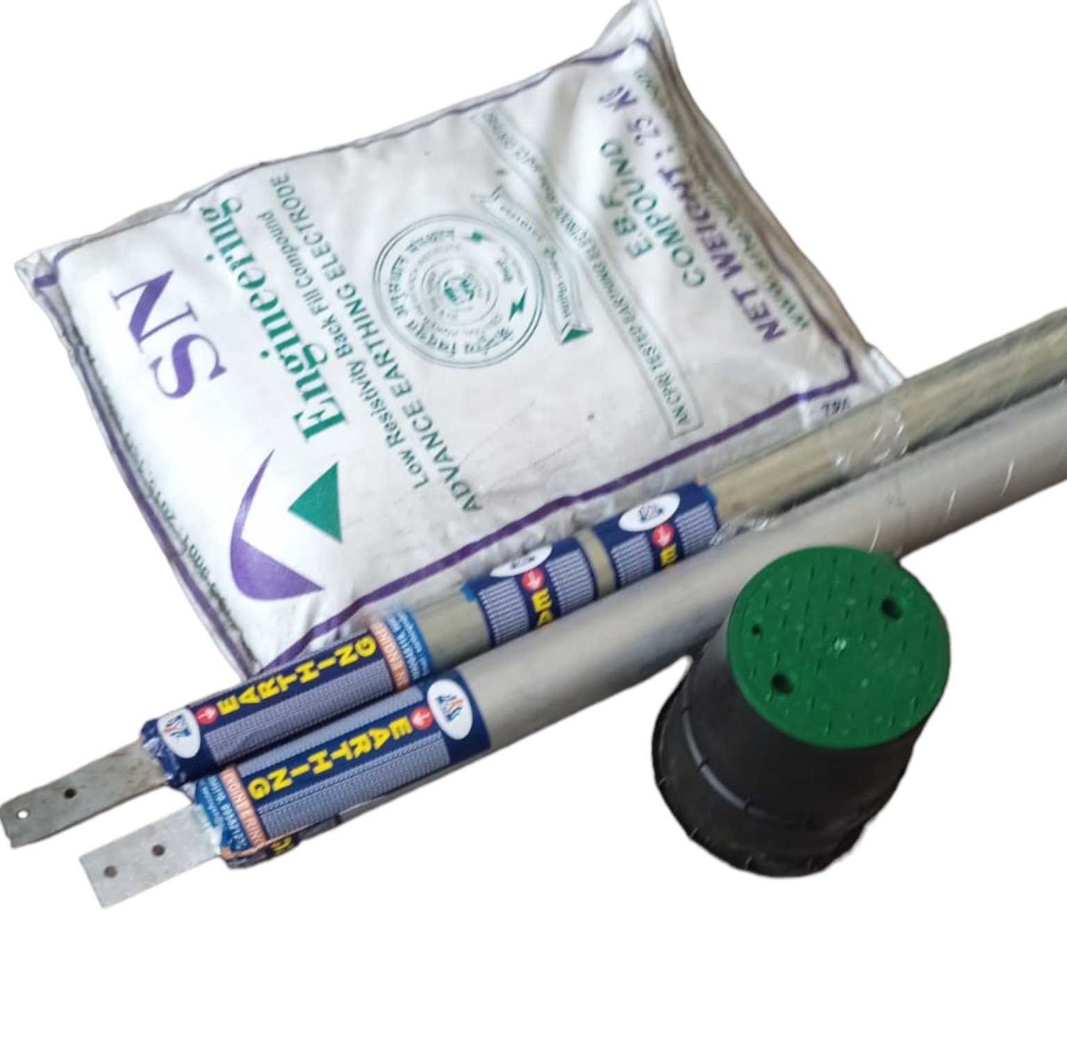
The final assembly should be selected through approved design data, soil resistivity, project specifications and site conditions.
SN Engineering’s chemical earthing package integrates an electrode, conductive backfill material, connection hardware, an inspection chamber and a testable grounding conductor termination.
A restrained technical gallery designed for procurement review, product selection and project documentation.
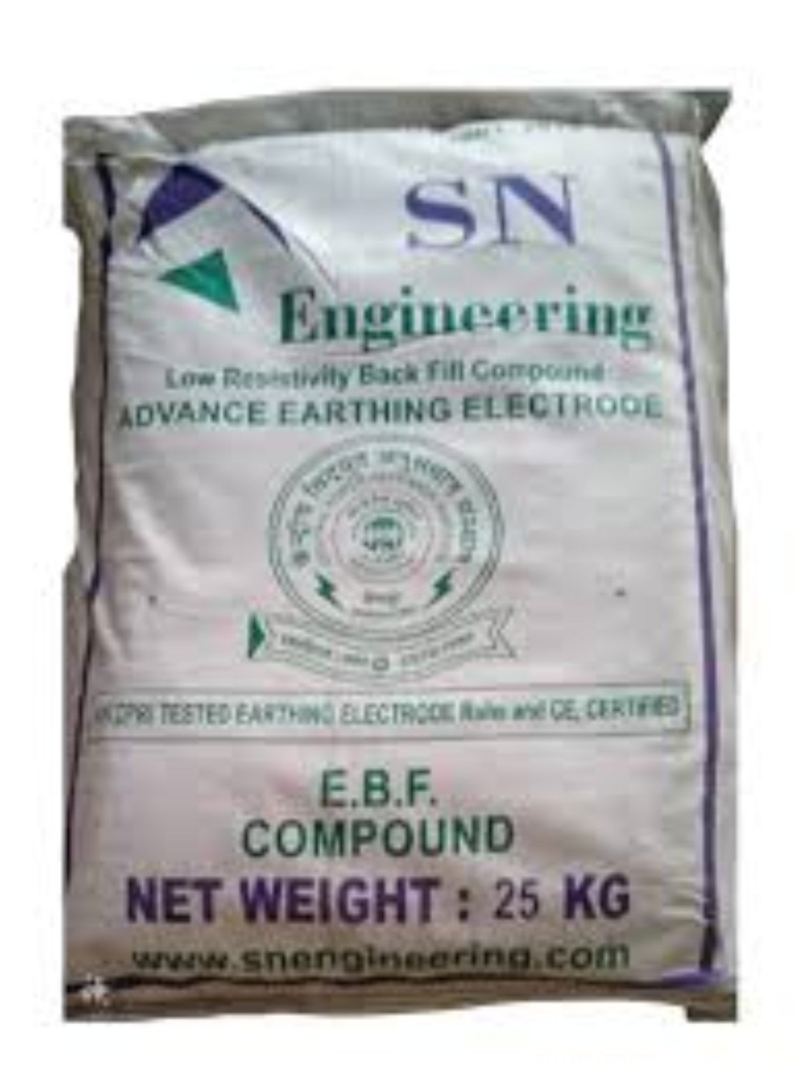
EBF Backfill Compound
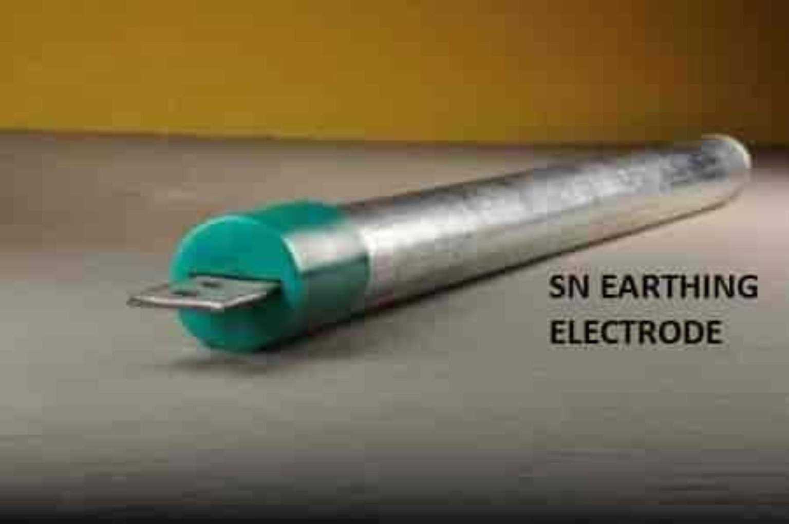
Electrode Assembly
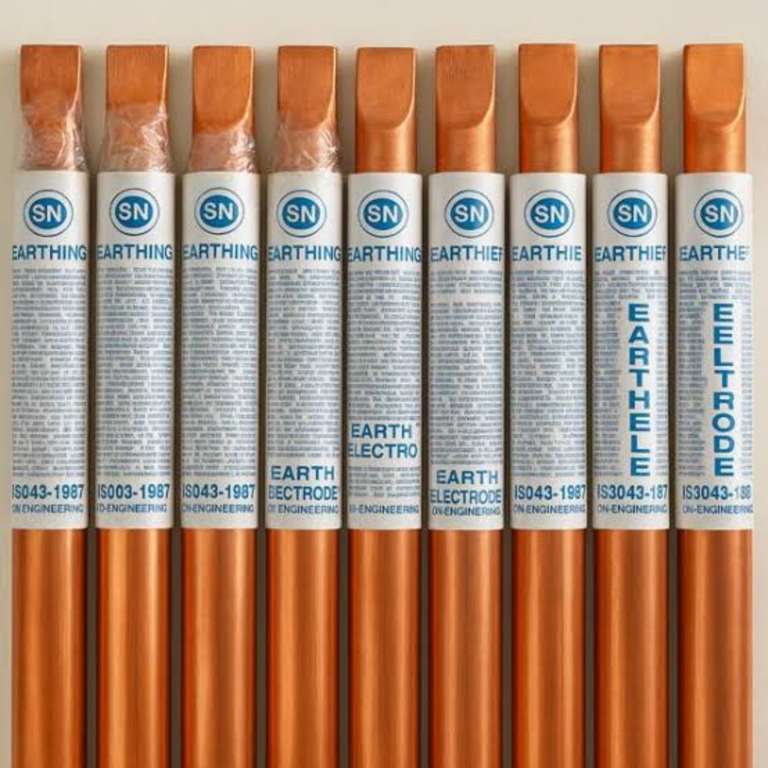
Representative electrode sizes and terminal configurations.

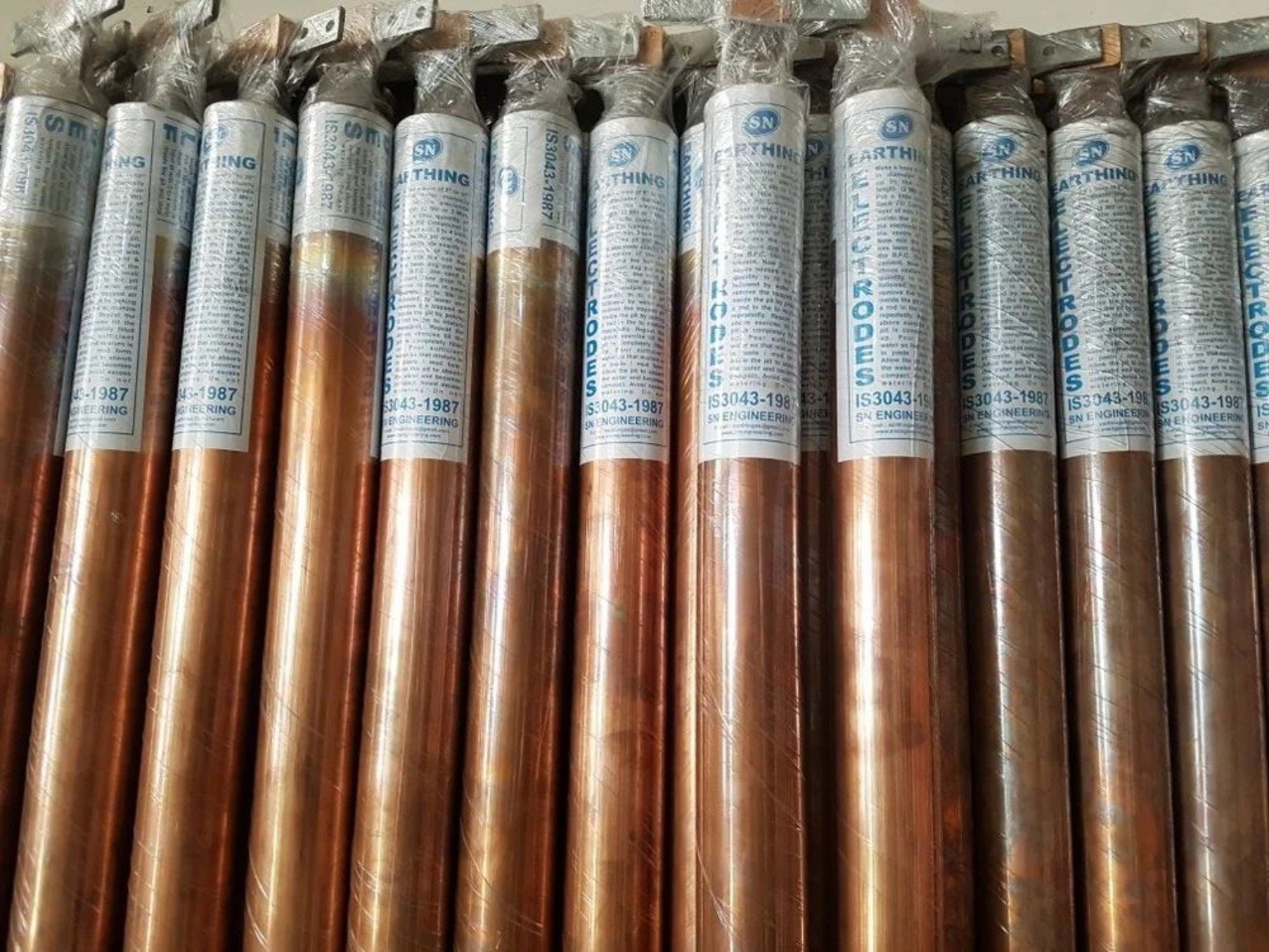
Protective packing and batch-ready supply.

Illustrative flat, clamp and project-specific terminations.
The page avoids invented values. Final dimensions, material, backfill quantity and acceptance resistance must come from approved technical documents.
Confirm the following before freezing the model:
| Electrode construction | Copper-bonded / copper / GI / approved project-specific construction. |
|---|---|
| Length and diameter | As per selected model and approved design. |
| Terminal arrangement | Flat, clamp, test link or custom project termination. |
| Backfill compound | Compatible EBF compound; quantity based on bore/pit geometry and approved method. |
| Connection conductor | Material and cross-section as per electrical design and fault-current requirement. |
| Acceptance resistance | As stated in the approved project specification and applicable authority requirement. |
| Inspection arrangement | Accessible chamber with testable and maintainable connection point. |
“Provide a complete chemical earthing system comprising a project-selected electrode, compatible low-resistivity backfill compound, corrosion-resistant connection hardware, accessible inspection chamber, testable earthing conductor termination, installation, testing and documentation. Electrode dimensions, conductor size, backfill quantity and target resistance shall comply with approved drawings, soil assessment, fault-current study, purchaser’s specification and applicable regulations.”
Confirm location, utilities, soil condition and approved layout.
Prepare dimensions as per the approved design and method statement.
Position vertically and protect coatings and terminal surfaces.
Place uniformly around the electrode without voids or contamination.
Install compatible hardware and secure testable termination.
Provide protected, labelled and accessible testing point.
Test continuity and earth resistance with calibrated instruments.
Record as-built details, photos, results and instrument information.
Factories, process facilities, utilities and electrical distribution systems.
Buildings, data centres, telecom, hospitals and institutional facilities.
Solar plants, generators, UPS systems and sensitive equipment installations.
No universal value should be promised without site data and approved design. Acceptance must follow the project specification and test method.
Quantity depends on electrode dimensions, bore/pit geometry, soil condition and the approved installation procedure.
Yes—only after verifying the tender number, issuing organisation, date and relevant clause from an official source.
Qualified personnel working under an approved method statement, electrical safety procedure and project inspection plan.
Share the soil report, project specification and required installation details.